Modelling and Control of an Aerial Manipulator
On this page I’ll present a summary of the work I did for my master’s thesis. Some of the work in the thesis was spun off into a paper, submitted to and accepted at the AIRPHARO 2021 Workshop on Aerial Robotic Systems Physically Interacting with the Environment.
The full thesis can be found here.
Abstract
Aerial robots have historically been used as flying eyes in the skies. Mounted with sensory payloads, they have been content to use their agility and range to see, smell, and listen to the world around them. More recently, research has begun to tackle the challenges of physical interaction. Unlocking this capability would enable UAVs to take on a much broader range of applications, including tasks which currently pose a risk of injury to the people performing them.
In this post, I’ll address the issue of performing physical interaction with the environment by a multi-rotor UAV implementing a basic cascaded position-attitude controller, typical of most of consumer-grade multi-rotor systems. More specifically, I identify mathematically the boundaries where the system can safely be used to perform physical interaction with the environment. These boundaries are then verified both in simulation and by experiment.
System Modelling
It is convenient to start by laying out the assumptions that I make while building the mathematical model of the drone platform in flight and in contact with the environment.
Assumptions
- The manipulator is of negligible mass and rigidly attached to the center of mass of the UAV.
- The UAV is assumed to be moving slowly enough, both in free-flight and in contact, for aerodynamic forces such as air resistance to be negligible.
- The contact surface is a plane parallel to the \( y,z \) plane of the inertial world frame.
- Contact between the UAV and the contact surface occurs ‘head on’, where the UAV is pitching, but roll, \( \theta \), and yaw, \( \psi \), are zero.
Nomenclature
(click to expand)
| Symbol | Description |
|---|---|
| \(W\) | The inertial world frame, fixed at some point in space |
| \(B\) | The body frame, fixed to the center of mass of the UAV |
| \(E\) | The end-effector frame, fixed to the tip of the manipulator |
| \({\xi}^\circ_\star\) | The position of the origin of frame \( \star \) w.r.t. frame \( \circ \). \( \xi^\circ_\star = \begin{bmatrix} x^\circ_\star & y^\circ_\star & z^\circ_\star \end{bmatrix}^T \) |
| \(\dot{\xi}^\circ_\star\) | The velocity of the origin of frame \( \star \) w.r.t. frame \( \circ \). \( \dot{\xi}^\circ_\star = \begin{bmatrix} \dot{x}^\circ_\star & \dot{y}^\circ_\star & \dot{z}^\circ_\star \end{bmatrix}^T \) |
| \(\ddot{\xi}^\circ_\star\) | The acceleration of the origin of frame \( \star \) w.r.t. frame \( \circ \). \( \ddot{\xi}^\circ_\star = \begin{bmatrix} \ddot{x}^\circ_\star & \ddot{y}^\circ_\star & \ddot{z}^\circ_\star \end{bmatrix}^T \) |
| \(R^\circ_\star\) | The rotation matrix representing the orientation of frame \(\star\) with respect to frame \(\circ\). |
| \(\eta\) | The euler angle parameterization of the orientation of the body frame with respect to the inertial frame. \( \eta = \begin{bmatrix} \phi & \theta & \psi\end{bmatrix}^T \) |
| \(\dot{\eta}\) | Time derivative of the euler angles. \( \dot{\eta} = \begin{bmatrix} \dot{\phi} & \dot{\theta} & \dot{\psi} \end{bmatrix}^T \) |
| \(\nu\) | Instantaneous angular velocity of the UAV with respect to the body frame. \( \nu = \begin{bmatrix} p & q & r \end{bmatrix}^T \) |
| \(\dot{\nu}\) | Instantaneous angular acceleration of the UAV with respect to the body frame. \( \dot{\nu} = \begin{bmatrix} \dot{p} & \dot{q} & \dot{r} \end{bmatrix}^T \) |
| \(m\) | The mass of the UAV |
| \(g\) | The acceleration due to gravity |
| \(\textbf{I}\) | The moment of inertia of the UAV |
| \(f^\circ\) | Force described in frame \(\circ\) |
| \(\tau^\circ\) | Torque described in frame \(\circ\) |
| \(S_\alpha, C_\alpha, T_\alpha\) | Shorthand for \(\sin(\alpha), \cos(\alpha), \tan(\alpha)\) |
General Model
For this work I considered a coaxial hexarotor platform with a rigidly attached manipulator. A diagram of the base platform without the manipulator is shown in fig 1. The manipulator is a rod of length \( L_m \) attached rigidly to the center of mass of the UAV, extending straight out between rotors 1 and 6, in the direction indicated by the red arrow, along the \( x \) axis.
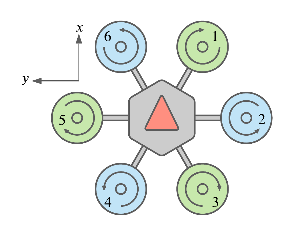 Fig. 1. Diagram of a coaxial hexarotor. The body frame \( B \) is attached to the center of mass of the UAV. The direction of the \( x \) and \( y \) axes are shown, the \( z \) projects out towards the reader. The rotors are arranged in counter-rotating pairs.
I define three frames of reference \( W \) , \( B \) , and \( E \), representing the inertial world frame, the body-fixed frame and the end-effector-fixed frame. It is useful to note that due to assumption 1, the axes of \( E \) are always parallel to the axes of \( B \).
( Click to see details )
The six rotors are arranged as shown in fig. 1. Each rotor is centered at a point $$ \mathbf{r}^B_i = L_r \begin{bmatrix} \cos(60i - 30) \\ -\sin(60i - 30) \\ 0 \end{bmatrix} $$ where \( L_r \) is the distance from the center of mass of the UAV to the center of each rotor. The \( i^{th} \) rotor generates a force \( \mathbf{f}^B_i \) and a torque \( \tau^B_i \) given by $$ \mathbf{f}^B_i = k \begin{bmatrix} 0 \\ 0 \\ \omega^2_i \end{bmatrix} \tag{1} $$ $$ \tau^B_i = S(\mathbf{r}^B_i) \mathbf{f}^B_i + b \begin{bmatrix} 0 \\ 0 \\ \omega^2_i \end{bmatrix} + I_M \begin{bmatrix} 0 \\ 0 \\ \dot{\omega_i} \end{bmatrix} \tag{2} $$ where \( \omega_i \) is the angular velocity of the \( i^{th} \) rotor, \( k \) is the lift constant, \( b \) is the drag constant, \( I_M \) is the moment of inertia of the rotor, and \( S(\cdot) \) maps a vector to its [skew symmetric matrix](https://en.wikipedia.org/wiki/Skew-symmetric_matrix). The derivative motor term \( I_M \dot{\omega_i} \) is omitted from the rest of the derivation due to it's small value. The total thrust force \( \mathbf{f}^B_t \) generated by the rotors is found by simply summing the various forces generated by each rotor. Due to the layout of the rotors on a coaxial multi-rotor, the force generated by each rotor occurs along the \( z \) axis of the body frame. The total thrust force then only has one non-zero component ( in \( B \) ) denoted \( T \). $$ \mathbf{f}^B_t = \sum^6_{i = 1} \mathbf{f}^B_i = \begin{bmatrix} 0 \\ 0 \\ T \end{bmatrix} \tag{3} $$ The total torque is calculated in the same way. $$ \tau^B_t = \sum^6_{i = 1} \tau^B_i = \begin{bmatrix} \tau_\phi \\ \tau_\theta \\ \tau_\psi \end{bmatrix} \tag{4} $$ The total wrench generated by the UAV is a vector with 6 elements, 3 elements of force and 3 elements of torque. Of these 6 elements, 4 of them are non-zero, the thrust force along the \( z \) axis and torques around each of the axes of \( B \). The reduced wrench vector \( \mathbf{w}^B_r \) contains only these active elements. $$ \mathbf{w}^B_{total} = \begin{bmatrix} \mathbf{f}^B_t \\ \tau^B_t \end{bmatrix} = \begin{bmatrix}0 \\ 0 \\ T \\ \tau_\phi \\ \tau_\theta \\ \tau_\psi \end{bmatrix} = \begin{bmatrix} 0 \\ 0 \\ \mathbf{w}^B_r \end{bmatrix} \tag{5} $$ The linear dynamics of the UAV in the inertial world frame \( W \) are given by $$ m \ddot{\xi}^W_B = \mathbf{f}^W_g + \mathbf{R}^W_B \mathbf{f}^B_t \tag{6} $$ where $$ \mathbf{f}^W_g = \begin{bmatrix} 0 \\ 0 \\ -mg \end{bmatrix} \tag{7}$$ is the force of gravity and \( \mathbf{R}^W_B \) is the rotation matrix, presenting the orientation of \( B \) with respect to \( W \). The rotation matrix \( \mathbf{R}^W_B\) is parameterized by \( \eta = \begin{bmatrix} \phi & \theta & \psi \end{bmatrix}^T \), using the [yaw-pitch-roll convention](https://en.wikipedia.org/wiki/Euler_angles#Tait%E2%80%93Bryan_angles). $$ \mathbf{R}^W_B = R_z (\psi) R_y (\theta) R_x (\phi) = \begin{bmatrix}C_\psi C_\theta & C_\psi S_\phi S_\theta - C_\phi S_\psi & S_\phi S_\psi + C_\phi C_\psi S_\theta \\ C_\theta S_\psi & C_\phi C_\psi + S_\phi S_\psi S_\theta & C_\phi S_\psi S_\theta - C_\psi S_\phi \\ -S_\theta & C_\theta S_\phi & C_\phi C_\theta\end{bmatrix} \tag{8} $$ where \( R_z (\psi) \) represents a rotation of \( \psi \) around the \( z \) axis, followed by \( R_y (\theta) \) around the new \( y \) axis and then \( R_x (\phi) \) around the final \( x \) axis. The inverse operation, that is the rotation matrix from the inertial frame to the body frame, is given by $$ R^B_W = \left(R^W_B\right)^{-1} = \left(R^W_B\right)^T $$ by the general properties of rotation matrices. Putting equations 3, 6, 7, and 8 together reveal the linear dynamics of the UAV $$ m \ddot{\xi}^W_B = \begin{bmatrix} T (S_\phi S_\psi + C_\phi C_\psi S_\theta) \\ -T (C_\psi S_\phi - C_\phi S_\psi S_\theta) \\ T C_\phi C_\theta - m g\end{bmatrix} \tag{9}$$ It's worth noting that, for the UAV to remain airborne, it needs to maintain zero acceleration along the \( z \) axis of the inertial frame \( W \). From equation 9, $$ m \ddot{z}^W_B = T C_\theta C_\phi - mg = 0 $$ Solving for \( T \) to find the thrust required to hover, reveals $$ T_{hover} = \frac{mg}{C_\theta C_\phi} \tag{10} $$ The rotational dynamics of the UAV in \( B \) are given by $$ \mathbf{I}\dot{\nu} + \nu \times (\mathbf{I}\nu) = \tau^B_t \tag{11} $$ Solving equation 11 for the angular acceleration \( \dot{\nu} \), $$ \dot{\nu} = \mathbf{I}^{-1}\left(\tau^B_t - \nu \times \left(\mathbf{I}\nu\right)\right) $$ The transformation from the angular velocity of the UAV with respect to \( W \) to the angular velocity of the UAV with respect to \( B \) can be expressed as a matrix \( \mathbf{W}_\eta \). $$ \nu = \mathbf{W}_\eta \dot{\eta} $$ $$ \dot{\eta} = \mathbf{W}^{-1}_\eta \nu $$ where $$ \mathbf{W}_\eta = \begin{bmatrix} 1 & 0 & -S_\theta \\ 0 & C_\theta & C_\theta S_\phi \\ 0 & -S_\phi & C_\theta C_\phi \end{bmatrix} $$ More details can be found in section 3.1 of the thesis on pages 6-9.The Newton-Euler equations of motion describing the UAV are:
\[m \ddot{\xi}^W_B = \mathbf{f}^W_g + \mathbf{R}^W_B \mathbf{f}^B_t\] \[\dot{\nu} = \mathbf{I}^{-1}\left(\tau^B_t - \nu \times \left(\mathbf{I}\nu\right)\right)\]Motor Mixer
At this point both the linear and rotational dynamics of the UAV have been derived and we are just about ready to move onto the contact model. Before we do so, I’m going to introduce the Motor Mixer Matrix. The Motor Mixer takes a set of desired forces and torques \( \mathbf{w}^B_r \) and outputs the (squared) motor speeds \( \Omega \) required to achieve them.
( Click to see details )
It is evident from equations 2 and 3 that the force and torque are functions of the squared rotor speeds. This fact carries through to equation 6. It is convenient for future derivations to take a look at the reduced wrench vector \( \mathbf{w}^B_r \) w.r.t. the squared motor speeds. First we define the vector \( \Omega \) to be the vector of squared motor speeds. $$ \Omega = \begin{bmatrix} \omega^2_1 \\ \omega^2_2 \\ \cdots \\ \omega^2_6 \end{bmatrix} $$ It is now possible to describe the reduced wrench vector as a function of \( \Omega \). $$ \mathbf{w}^B_r = \mathbf{J} \Omega $$ where \( \mathbf{J} \in \mathbb{R}^{4 \times 6} \) is the Jacobian of \( \mathbf{w}^B_r \) w.r.t. \( \Omega \). The pseudo-inverse of the Jacobian $$ M = J^+ $$ is called the motor mixer matrix and maps some reduced wrench to the (squared) rotor speeds required to achieve it. More details can be found in section 3.3.1 of the thesis on pages 14-17.Contact Model
For the contact model, I consider the UAV with its end-effector in contact with the wall. The UAV is considered to be in static equilibrium, that is, not moving or accelerating, linearly or rotationally. The goal of the contact model is to identify the limits of the UAVs ability to maintain contact and a static equilibrium, a state I refer to as static contact.
I found that the UAVs ability to maintain static contact is defined by two limits. The first is a requirement that the friction force experienced by the end-effector is sufficient to prevent the end-effector from slipping. The second is the limit of the UAVs ability to counteract the reaction torque from the contact forces experienced by the end-effector.
( Click to see details )
As the UAV applies a force on the wall, a countervailing force is applied on the end-effector of the UAV. This force is made up of two parts, a normal force and a friction force. The normal force, on the other hand, works to prevent the end-effector from penetrating the contact surface. The friction force occurs parallel to the contact surface and works to prevent the end-effector from slipping along the wall. The magnitude of the force of friction is proportional to the normal force. From assumption 3 it follows that the contact force experienced by the UAV at the end-effector is, $$ \mathbf{f}^W_c = \begin{bmatrix} f_n \\ f_{f,y} \\ f_{f,z} \end{bmatrix} $$ During static contact the following must be true, $$ \lvert f_f \rvert \leq \mu \lvert f_n \rvert $$ When the UAV is in static contact with the wall, $$ m \ddot{\xi}^W_B = \mathbf{f}^W_g + \mathbf{R}^W_B \mathbf{f}^B_t + \mathbf{f}^W_c = 0$$ $$ \mathbf{f}^W_c =-\mathbf{f}^W_g - \mathbf{R}^W_B \mathbf{f}^B_t = \left\lbrack\begin{array}{c} -T(S_\phi S_\psi + C_\phi C_\psi S_\theta) \\ -T(C_\phi S_\psi S_\theta - C_\psi S_\phi) \\ -T C_\phi C_\theta+m g\end{array}\right\rbrack $$ where T is the thrust force generated by the UAV. Applying assumption 4 and the friction inequality reveal the limits imposed by friction of the UAVs ability to maintain static contact. $$ \lvert T C_\theta - m g \rvert \leq \mu \lvert T S_\theta \rvert $$ 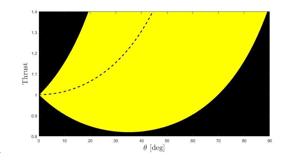 Fig 2. Friction Bound The yellow region represents the region of thrust force and pitch angle where the friction force is large enough to prevent the end-effector from slipping along the wall. The yellow region is plotted with \(\mu=0.7\).
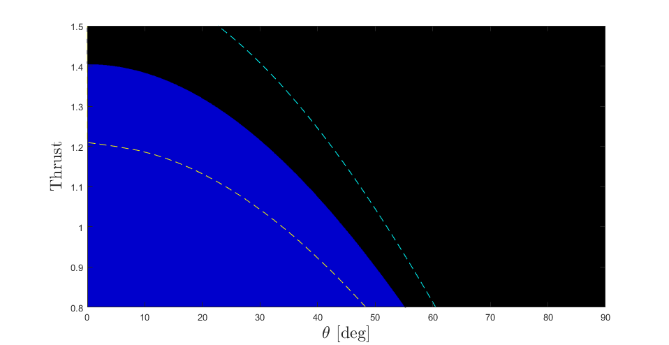 Fig 3. Torque Bound The blue region represents the region of thrust force and pitch angle in which the UAV is capable of counteracting the reaction torque on the UAV from contact. Outside of this region, the UAV is unable to maintain its orientation and will begin to pitch into the wall. The blue region is plotted with \(s_{mr} = 2\), the yellow and cyan dashed lines represent \(s_{mr}=1.5\) and \(s_{mr}=3.4\) respectively.
The operating region of the UAV is the region of thrust force and pitch angle in where both the friction bound and the torque bound are satisfied.
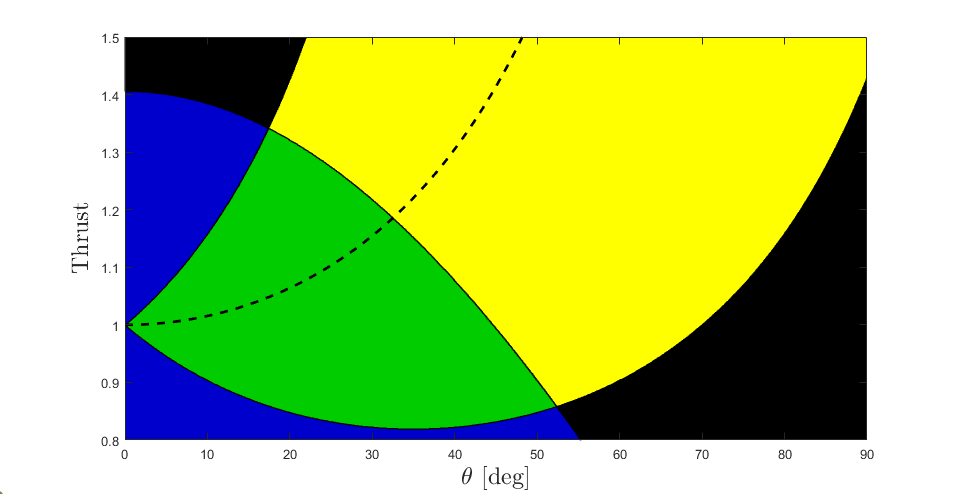 Fig 4. Operating Region Shown in green, the region of Thrust Force and Pitch in which the UAV is physically capable of maintaining static contact with the wall.
Controllers in Contact
To understand how our control scheme affects the UAVs operating region, I’ll start by defining the controllers. The position control scheme used for this thesis was a cascaded PID control scheme, with an outer PD position control loop feeding attitude references into an inner PD attitude control loop, which, along with a PD altitude controller passed a reduced wrench to the Motor Mixer.
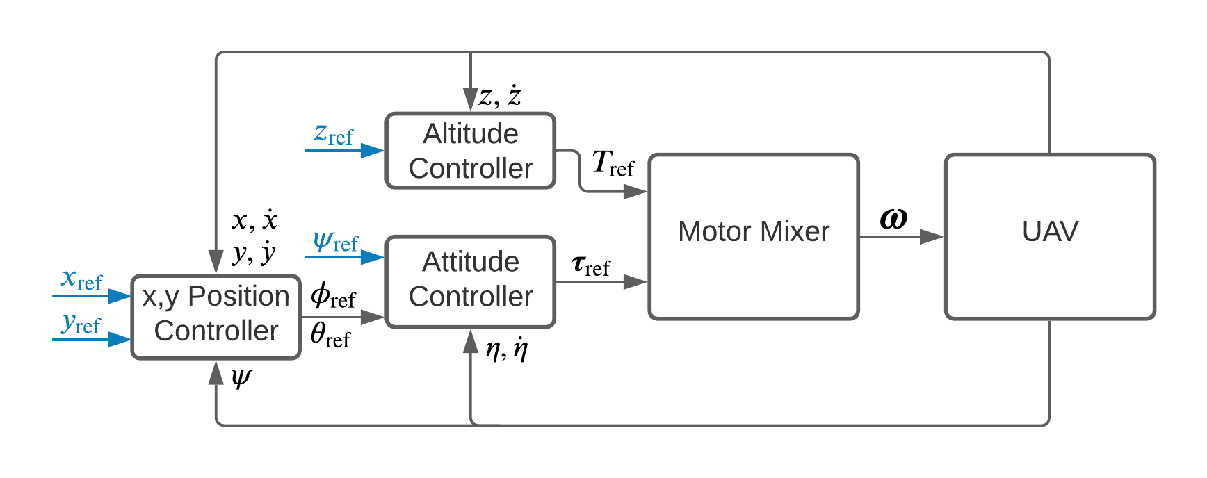 Fig 5. Cascaded Position Controller
The altitude controller, attitude controllers, and position controllers were implemented as follows:
\[T_{ref} = \frac{1}{C_\phi C_\theta} (k_{p,z} e_{p,z} + k_{d,z} e_{d,z} + m g)\] \[\tau_{ref} = \mathbf{K}_{p,\eta} \mathbf{e}_{p,\eta} + \mathbf{K}_{d,\eta} \mathbf{e}_{d,\eta}\] \[\phi_{ref} = - (k_{p,y} e'_{p,y} + k_{d,y} e'_{d,y} )\] \[\theta_{ref} = k_{p,x} e'_{p,x} + k_{d,x} e'_{d,x}\]It’s practical to note that the derivative error terms \(e_{d,\cdot}\) for all of the controllers become zero when the UAV is in static contact.
( Click to see details )
I'll start with the attitude controller. The attitude controller needs to counteract the reaction torque, $$ \tau^B_\theta = k_{p,\theta} e_{p,\theta} = k_{p,\theta} (\theta_{ref} - \theta) = L_m (T_ref - m g C_\theta) $$ The altitude controller controls the thrust force generated by the UAV. Holding \( z_{ref} \) constant, $$ z^W_B = z_{ref} + L_m S_\theta $$ Plugging this into the altitude controller, $$ T_{ref} = \frac{1}{C_\theta} (k_{p,z} (z_{ref} - z^W_B) + m g ) = \frac{m g}{C_\theta} - \frac{k_{p,z} L_m S_\theta }{C_\theta} $$ I now rearrange the attitude controller equations to solve for the pitch angle reference, $$ \theta_{ref} = \theta - \frac{L_m ( m g C_\theta - T_{ref}) } {k_{p,\theta}} $$ Fig. 6 shows the plot of \( \theta_{ref} \) as a function \( \theta \). We can see that there is an inflection point at (in this case) \(theta = 24.2^\circ \). This represents the limit of the controllers ability to command the UAVs torque.  Fig 6. Pitch Control Limit Reference pitch \( \theta_{ref} \) (in blue) required for stationary contact as a function of pitch angle \( \theta \). The black dashed line represents the mapping in free-flight, the identity function.
Fig. 7 shows the realisable region of thrust force and pitch angle in pink. Within the realisable region (pink), the attitude controller of the UAV is capable of commanding the torque required to maintain static contact. This region is a subset of the operating region (green) in which the UAV is physically capable of maintaining static contact. The operating region is the union of the friction and torque bounds, outside of which either the end-effector slips along the wall (blue) or the UAV pitches uncontrollably into the wall (yellow).
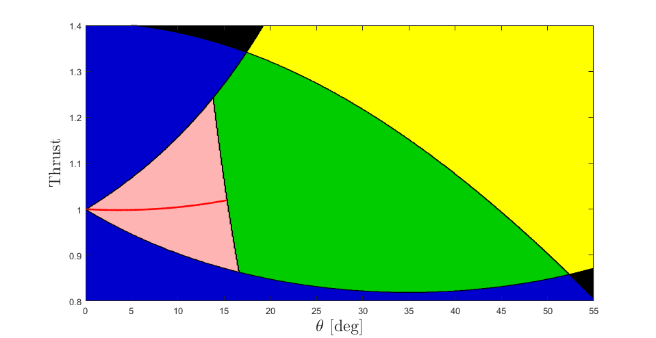 Fig 7. Realisable Region The region of Thrust Force and Pitch in which the PID attitude controller of the UAV is capable of maintaining static contact with the wall.
This figure is really the crux of this thesis and the corresponding article, showing the limits on the UAV from both the physical design and construction, as well as from controller design.
Verification
Now that we have all of the mathematical modelling out of the way, we can take a look at the simulations and the experiments that were performed.
Simulation
I created several simulation models of the UAV in MATLAB and Simulink using the Simscape Multibody Toolbox.
Fig. 8 plots the pitch angle over time. Fig. 9 plots the trajectory of the UAVs pitch angle and thrust force throughout the simulation. The red line in Fig. 9 corresponds with the section of fig. 8 before the red dashed line, the cyan in fig. 9 corresponds to the section after the red dashed line.
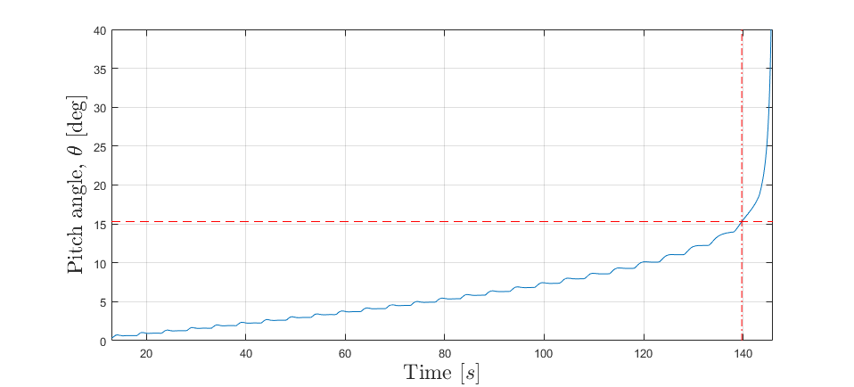 Fig. 8 Simulated Pitch Angle Plot of the pitch angle \(\theta\) during simulation. The dashed lines represent the inflection point and time of occurrence.
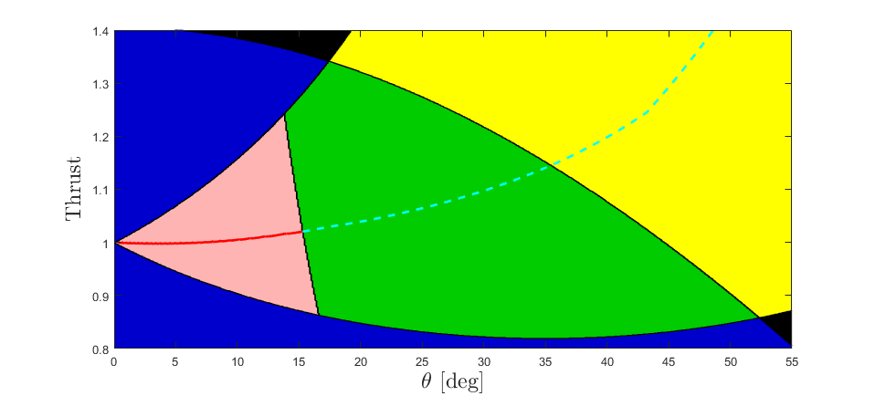 Fig. 8 Simulated Path Plot showing the path of the UAV through the regions of pitch angle and thrust force. The red shows the UAVs path while under control. The cyan dashed line shows the path taken by the UAV past the inflection point.
Experiment
The final touch to the thesis are the experiments. I spent months building and programming (and rebuilding) the physical hexarotor platform. I’d like to say that this project was done in the right order, starting with the mathematical model, followed by the simulation model and finally experiments on the physical platform for verification. In truth, the process was more complicated.
I started with building and programming the physical platform, before being interrupted by the COVID-19 lockdowns. I moved on to my simulation models, and, when I was able to return to the lab, began experimenting with the contact flight tests. The flight tests by themselves told me only that the UAV could initiate and maintain contact with a surface up to some extent. It was only as I began writing the thesis itself that I began to realise how to approach the problem statement I had started with. Working through inconsistencies between the mathematical and simulation models enabled me to identify the effects of the attitude controller on the realisable region of the UAV.
It was only the final month of the thesis writing process, armed with my mathematical description of contact, validated by simulation, that I returned to all of my contact flight test data. After digging through dozens of flight tests, I was able to find one which cleanly encapsulated the findings of this thesis and which I also had a video of, so without further ado:
Impressive, right? We see the UAV initiate contact three times, the first two attempts result in the end effector sliding down the wall. The third attempt results in the UAV pitching and yawing uncontrollably. Fine, maybe its not so impressive. The important thing is that I now have a theory to explain why and how it failed each time.
The first two contacts result in sliding, which occurs if the UAV slips out of the friction bound. Seeing as the end-effector slides down, I can go further and say that the UAV slips below the friction bound. The final contact results in uncontrolled pitching (and yawing) which implies that the UAV has moved outside of the realisable region, while staying within the friction bound. Figs. 10, 11 and 12 show the paths of the UAV for the first, second and third contacts, respectively.
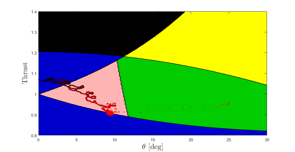 Fig. 10 First Contact The UAV slips below the friction bound, causing the end-effector to slide down the wall
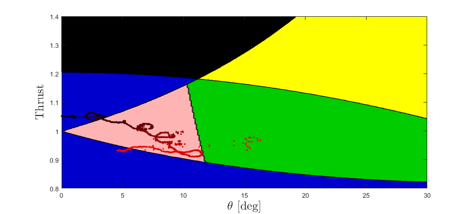 Fig. 11 Second Contact The UAV slips below the friction bound, causing the end-effector to slide down the wall
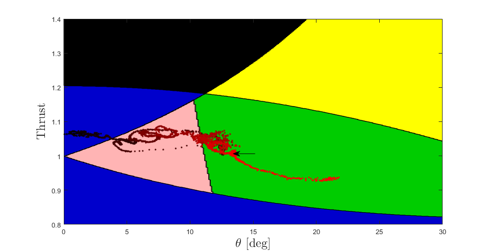 Fig. 12 Third Contact The UAV moves beyond the realisable region and begins to pitch uncontrollably
Conclusion
The conclusions to be drawn from this thesis are two-fold. First, I found a method to map the limits of a standard coplanar hexarotor platform with a rigid manipulator in head-on contact with its environment. The analysis done in the thesis, while specific to hexarotors, can easily be extended to any coplanar UAV configuration. Second I identified which design parameters of the UAV effect the limits of the UAV. To increase the limit on the contact force, a drone designer can increase the mass of the UAV, shorten the manipulator, increase the distance between the rotors and the center of mass of the UAV, or increase the proportional gain on the PID attitude controller.